Introduction
Digital circuits often rely on microcontrollers, sensors, and other components to process inputs and produce outputs. However, a common issue in digital logic systems is the presence of floating inputs, which can cause erratic behavior. This is where pull-up and pull-down resistors come into play. These simple resistors help establish a known logic level and ensure circuit reliability.
In this article, we’ll explore what pull-up and pull-down resistors are, why they are necessary, when to use them, how to choose the right values, common mistakes to avoid, and advanced applications in circuit design. By the end, you’ll have a solid understanding of these essential components and their role in digital circuits.
What Are Pull-up and Pull-down Resistors?
Pull-up and pull-down resistors are used in digital circuits to ensure that an input pin has a defined voltage level when no active driving signal is present.
- Pull-up resistor: Connects an input pin to VCC (high voltage level), ensuring it reads as logic HIGH (1) when not actively driven LOW.
- Pull-down resistor: Connects an input pin to GND (low voltage level), ensuring it reads as logic LOW (0) when not actively driven HIGH.
These resistors typically have values ranging from 1kΩ to 100kΩ, depending on the application.
The Problem of Floating Inputs
Digital inputs have three possible states: HIGH (1), LOW (0), and floating (undefined). A floating input is not connected to a fixed voltage and can randomly pick up noise from the environment, leading to unpredictable behavior. This can cause a microcontroller to misinterpret signals, resulting in faulty operations.
Pull-up and pull-down resistors eliminate this issue by ensuring that a pin always has a default state when it is not actively driven.
When to Use Pull-up and Pull-down Resistors
Let’s look at some practical cases where these resistors are essential.
1. Using Pull-up Resistors for Button Inputs
A common use case is when interfacing buttons with microcontrollers. Consider a push-button connected to a GPIO pin. When the button is not pressed, the input pin is floating, which can cause erratic readings.
By adding a pull-up resistor (typically 10kΩ) between the input pin and VCC, the pin is kept HIGH by default. When the button is pressed, it connects the pin directly to GND, pulling it LOW. This ensures a clean transition between HIGH and LOW states.
Example Circuit:
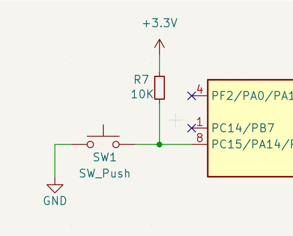
Why use a pull-up resistor?
- Ensures the button pin reads HIGH when unpressed.
- Avoids erratic floating values.
2. Using Pull-down Resistors for Active-High Inputs
Sometimes, you may need a button or sensor to be active-high, meaning it sends a HIGH signal when triggered. In this case, you use a pull-down resistor (typically 10kΩ) to ensure the pin defaults to LOW.
Example Circuit:
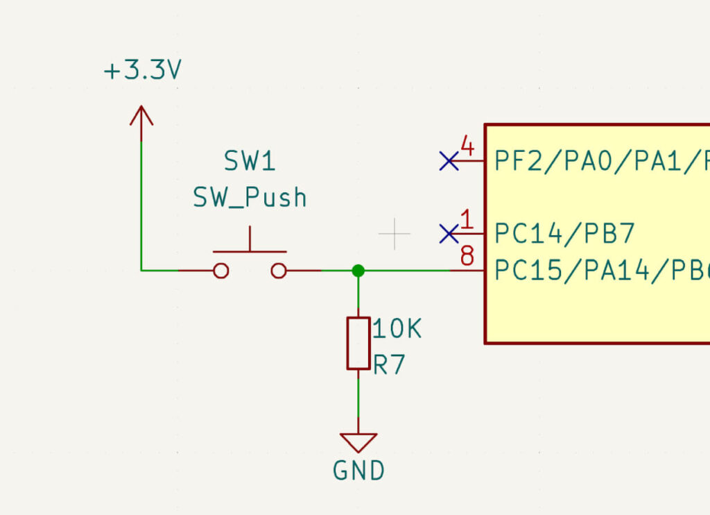
Why use a pull-down resistor?
- Ensures the pin reads LOW when the button is unpressed.
- Prevents unintended HIGH signals due to floating inputs.
3. Pull-up Resistors in I2C Communication
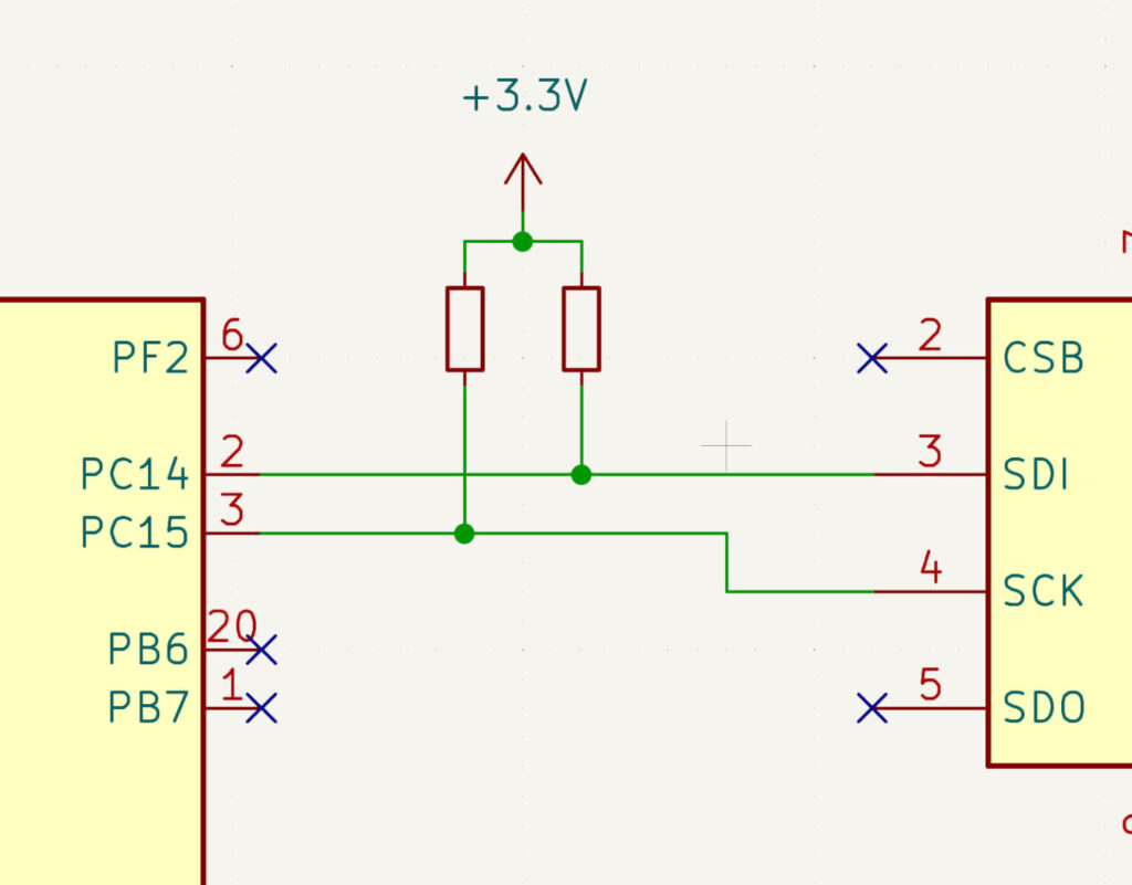
In I2C communication, SDA (data) and SCL (clock) lines require pull-up resistors to function correctly. Without them, the lines might remain floating, leading to unreliable communication between master and slave devices.
Standard Values:
- 4.7kΩ to 10kΩ pull-up resistors on both SDA and SCL lines.
- Ensure stable HIGH signals and proper logic level detection.
Why use pull-ups in I2C?
- Keeps the lines at a known HIGH state when no device is pulling them LOW.
- Ensures clean and reliable data transmission.
4. Microcontroller Internal Pull-up Resistors
Most modern microcontrollers, including Arduino, ESP32, and PIC, have internal pull-up resistors that can be enabled via software. This eliminates the need for external resistors in some cases.
For example, in an Arduino, you can enable an internal pull-up resistor with:
pinMode(pin, INPUT_PULLUP);
This is particularly useful for button and switch inputs, reducing the need for additional components.
Choosing the Right Resistor Value
The value of a pull-up or pull-down resistor affects both power consumption and signal integrity:
- 1kΩ to 4.7kΩ: Strong pull, faster response, but higher power consumption.
- 10kΩ (common value): Balanced performance.
- 47kΩ to 100kΩ: Weak pull, lower power consumption, but slower response.
For most button and GPIO applications, 10kΩ is a good choice. For high-speed signals like I2C, lower values (4.7kΩ) are recommended.
Other Applications
Beyond basic button and communication applications, pull-up and pull-down resistors are crucial in other areas:
- Reset circuits: Ensuring microcontrollers start in a defined state.
- Open-drain outputs: Used in bus systems like I2C and SPI.
Clock signal stabilization: Preventing glitches in sensitive circuits.
Common Mistakes to Avoid
- Using Both Pull-up and Pull-down Resistors on the Same Pin
- This creates a voltage divider, resulting in an undefined logic level.
- Choosing Incorrect Resistor Values
- A very high resistance (e.g., 1MΩ) may fail to pull the pin reliably.
- A very low resistance (e.g., 100Ω) may consume excessive power.
- Forgetting to Enable Internal Pull-ups When Needed
-
- Some microcontrollers have built-in pull-ups but require activation via code.
-
Conclusion
Pull-up and pull-down resistors are essential for ensuring stable and predictable logic levels in digital circuits. They prevent floating inputs, reduce noise issues, and improve circuit reliability. Whether you’re working with buttons, sensors, or communication protocols like I2C, understanding when and how to use these resistors is crucial.