Power supplies are crucial components in electronic systems, converting raw input power into a stable and usable form for various circuit components. Two primary types of power supply designs are linear regulators and switching regulators. A good and clear understanding of these supplies will help you, as an electronics design engineer, to design efficient circuits and know when to leverage one over the other.
When designing a new board, it’s to choose an adequate power supply, and consider its broader impact and potential pitfalls on the board. For example, certain supply topologies can generate significant noise in the circuit, potentially affecting other sections of your design.
To avoid these pitfalls, engineers must have a proper understanding of power supply design. This article illustrates the characteristics, advantages, and disadvantages of each type, offering guidance on how to select the appropriate power supply for your design needs.
Linear regulators are a fundamental component in power supply design, particularly for low-power applications. They operate by using a transistor, which adjusts its resistance to maintain a constant output voltage regardless of variations in the input voltage or the load. The regulation process involves continuously dropping excess voltage across the transistor, which is why linear regulators are often associated with heat generation.
One of the key reasons to use linear regulators in low-powered devices is their simplicity and ability to provide clean, noise-free power. They do not require inductors or complex circuitry, making them easy to design and integrate into your system. Their low noise output is especially important in applications where power supply noise could interfere with sensitive analog or RF circuits.

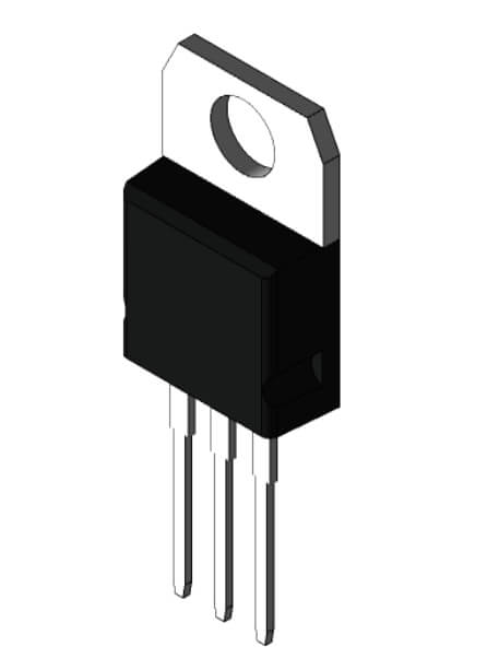
The 7805 is a popular linear voltage regulator that outputs a stable 5V, ideal for powering microcontrollers and 5V logic devices.
Imagine you’re designing a small embedded system that runs on a 9V battery. You can use a 7805 voltage regulator to step down the 9V to a stable 5V. The 7805 is effective for providing a clean and consistent 5V power supply, ensuring that your system operates reliably.
In summary, the 7805 linear voltage regulator is an excellent choice for providing a stable 5V in low-power designs. However, careful consideration must be given to the input voltage to minimize heat generation. Ensuring the input voltage is not excessively higher than the output and providing adequate cooling, if necessary, are key to maintaining the efficiency and longevity of your design.
Switching regulators, or switch-mode power supplies (SMPS), are highly efficient and versatile systems, making them a popular choice for a wide range of applications. Unlike linear regulators, which dissipate excess energy as heat, switching regulators convert input power by rapidly switching on and off a pass element (usually a transistor) and storing energy in inductors or capacitors.
They are required in scenarios where high efficiency is critical, such as battery-powered devices or high-power applications. Their ability to operate with a wide range of input voltages and deliver consistent output makes them ideal for these environments.

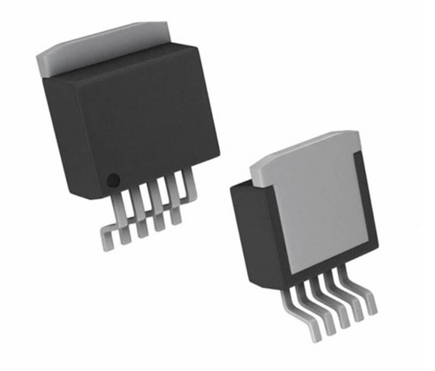
IL2596-ADJD2T-P Switching Regulator IC
However, this efficiency comes at the cost of increased complexity. They require careful design to manage the switching noise they generate, which can interfere with sensitive circuit sections. They also require more components, such as inductors and capacitors, which add to the design complexity and potential cost. Furthermore, electromagnetic interference (EMI) is a common challenge with switching regulators, laying out your PCB in the proper way helps in better design yields.
To ensure your power supply design is error-free, using CADY software offers a significant advantage. . CADY can map the power nets in your design to their sources, and calculate their actual voltage level based on its unique AI understanding of power supply components’ datasheets. Thus, CADY can detect potential capacitor breach, supply pins connected to inadequate supply voltage, wrong power net names and more.
CADY has been a game-changer for many HW engineers, helping them identify and correct errors before they become costly issues. For better design outcomes, integrating CADY into your workflow is a smart move.